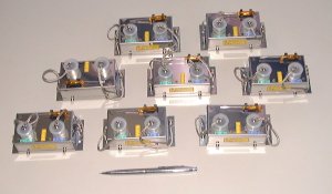
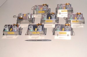
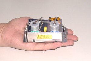
Performance is shown below. The numerical value, that mV/V that shows it also, below did 2000 times becomes a
strain display ( Ęs).
[Power supply] The use power supply is specified to an/the amplifier.
The power supply supplies it from an/the input-output connector.
AC100V, DC10`16V, DC } 6`15V etc. are a standard article.
[Bridge voltage] AC1`2VRMS, 4`6KHZ.
[Sensor]
The object sensor is a distortion gauge ceremony.
It is as follows by input amplifier gain resistance.
Rin=50 ķ in, rating output the sensor of 2mV/the V following
Rin=200 ķ in, rating output the sensor (the standards) of 8mV/the V following
Rin=500 ķ in, rating output the sensor of 20mV/the V following
[Output]
Output differs by the use power supply and also output ATT.
The output of this amplifier is calculated with the next ceremony.
Output=(sensor output/ bridge voltage) *magnification mV
Output ATT is as follows by Rin.
Rin=50 ķ in, rating output*2000 times
Rin=200 ķ in, rating output*500 times (the standards)
Rin=500 ķ in, rating output*200 times
[Zero balance] An adjustment range is as follows by input amplifier balance resistance.
R bala =5K ķ in, } (sensor input resistance/100)*5mV/V (the standards)
R bala =50K ķ in, } (sensor input resistance/100)*0.5mV/V
[Output ATT] Output voltage adjustment.
The correction certificate of the report card and also ISO system are attached.


